924K, 926M, 930K, 930M, 938K and 938M Wheel Loaders Information Display
– CAN Data Link – Test
– Data Link
– Determining Diagnostic Trouble Codes
– Diagnostic Capabilities
– Diagnostic Trouble Codes
– Display Menu
– Event Codes
– General Information
– General Information
– Machine Menu
– Menu Navigation
– Module – Flash Program
– Operator Menu
– Pop-Up Messages
– Sensor (Data Link Type) – Test
– Sensor Supply – Test
– Service Menu
– Service Tools
– System Schematic
– Totals Menu
– Wiring Harness (Open Circuit) – Test
– Wiring Harness (Short Circuit) – Test
Automatic Lubrication System for Small Wheel Loaders
– Automatic Lubrication System – Charge
– Automatic Lubrication System – Flush
– Automatic Lubrication System – Test
– Automatic Lubrication System Troubleshooting
– General Information
– Lubrication Distribution Valve
– Lubrication Pump
– System Pressure – Release
Disassembly and Assembly 926M, 930M and 938M Wheel Loaders Engine Supplement
– Aftercooler – Remove and Install
– Air Cleaner – Remove and Install
– Alternator – Remove and Install
– Battery – Remove and Install
– Belt Tensioner – Remove and Install
– Clean Emissions Module – Remove and Install
– Cooling System Package (Radiator, Aftercooler, Hydraulic Oil
– Crankshaft Front Seal – Remove and Install
– Crankshaft Vibration Damper and Pulley – Remove and Install
– DEF Injector and Mounting – Remove and Install
– Diesel Exhaust Fluid Filter – Remove and Install
– Diesel Exhaust Fluid Module – Assemble
– Diesel Exhaust Fluid Module – Disassemble
– Diesel Exhaust Fluid Module – Remove and Install
– Diesel Exhaust Fluid Pump – Remove and Install
– Disconnecting Snap To Connect Fittings
– Electric Starting Motor – Remove and Install
– Electronic Control (Diesel Exhaust Fluid) – Remove and Install
– Engine – Remove and Install
– Engine Control Module – Remove and Install
– Engine Mount – Remove and Install
– Engine Oil Filter Base and Oil Cooler – Remove and Install
– Engine Oil Pan – Remove and Install
– Exhaust Back Pressure Valve – Remove and Install
– Fan – Remove and Install
– Fuel Filter (Secondary) and Fuel Filter Base – Remove and
– Fuel Priming Pump and Primary Filter (Water Separator) –
– Fumes Disposal Filter – Remove and Install
– Gear Motor (Hydraulic Fan) – Assemble
– Gear Motor (Hydraulic Fan) – Disassemble
– Gear Motor (Hydraulic Fan) – Remove and Install
– Hood – Remove and Install
– Hydraulic Oil Cooler – Remove and Install
– Manifold (DEF Heater) – Remove and Install
– Nitrogen Oxide Sensor – Remove and Install – Nitrogen Oxide
– Radiator and Fuel Cooler – Remove and Install
– Radiator Top Tank – Remove and Install
– Refrigerant Compressor – Remove and Install
– Refrigerant Condenser – Remove and Install
– Solenoid Valve (DEF Heater Coolant) – Remove and Install
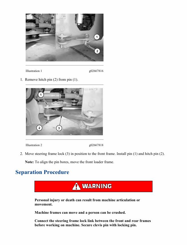
– Steering Frame Lock – Separate and Connect
– System Pressure – Release
– System Pressure – Release
– Temperature Sensor (DPF Inlet, Flame Detect) – Remove and
– Torsional Coupling – Remove and Install – Type 1
– Torsional Coupling – Remove and Install – Type 2
– Turbocharger – Remove and Install
– Valve Mechanism Cover – Remove and Install
– Voltage Control (Load Protection) – Remove and Install
– Water Pump – Remove and Install
– Water Temperature Regulator – Remove and Install
Disassembly and Assembly 926M, 930M and 938M Wheel Loaders Machine Systems
– Accumulator (Pilot) – Remove and Install
– Brake Accumulator – Remove and Install
– Brake Control Valve (Parking) – Assemble
– Brake Control Valve (Parking) – Disassemble
– Brake Control Valve (Parking) – Remove and Install
– Brake Control Valve (Service) – Assemble
– Brake Control Valve (Service) – Disassemble
– Brake Control Valve (Service) – Remove and Install
– Cab – Remove and Install
– Control Manifold (Brake Charge) (Hydraulic Fan Control) –
– Control Manifold (Brake Charge) (Hydraulic Fan Control) –
– Control Manifold (Brake Charge) (Hydraulic Fan Control) –
– Counterweight – Remove and Install
– Disconnecting Snap To Connect Fittings
– Electrohydraulic Control (Joystick) – Remove and Install
– Electronic Control Module – Remove and Install – Machine
– Fuel Tank – Remove and Install
– Gear Pump (Hydrostatic, Charge) – Assemble
– Gear Pump (Hydrostatic, Charge) – Disassemble
– Gear Pump (Hydrostatic, Charge) – Remove and Install
– Heating and Air Conditioning Unit – Assemble
– Heating and Air Conditioning Unit – Disassemble
– Heating and Air Conditioning Unit – Remove and Install
– Hydraulic Oil Filter – Remove and Install
– Hydraulic Tank – Assemble
– Hydraulic Tank – Disassemble
– Hydraulic Tank – Remove and Install
– Instrument Panel – Remove and Install
– Lift Arms – Remove and Install
– Lift Cylinder – Remove and Install
– Loader Frame from Rear Frame – Separate
– Loader Frame to Rear Frame – Connect
– Main Control Valve – Assemble
– Main Control Valve – Disassemble
– Main Control Valve – Remove and Install
– Metering Pump (Steering) – Remove and Install
– Parking Brake – Assemble
– Parking Brake – Disassemble
– Parking Brake – Remove and Install
– Piston Pump (Implement) – Assemble
– Piston Pump (Implement) – Disassemble
– Piston Pump (Implement) – Remove and Install
– Piston Pump (Steering) – Assemble
– Piston Pump (Steering) – Disassemble
– Piston Pump (Steering) – Remove and Install
– Refrigerant Accumulator – Remove and Install
– Ride Control Accumulator – Remove and Install
– Seat – Remove and Install
– Secondary Steering Pump and Electric Motor – Remove and
– Steering Cylinder – Remove and Install
– Steering Frame Lock – Separate and Connect
– Steering Frame Lock – Separate and Connect
– Steering Shaft – Remove and Install
– Steering Wheel – Remove and Install
– System Pressure – Release
– System Pressure – Release
– Tilt Cylinder – Remove and Install
– Tilt Lever – Remove and Install
– Tilt Link – Remove and Install
– Water Valve (Cab Heater) – Assemble
– Water Valve (Cab Heater) – Disassemble
– Water Valve (Cab Heater) – Remove and Install
– Window Wiper and Wiper Motor (Front) – Remove and Install
– Window Wiper and Wiper Motor (Rear) – Remove and Install
Disassembly and Assembly 926M, 930M and 938M Wheel Loaders Power Train
– Accumulator – Remove and Install – Hydrostatic
– Axle Housing – Install – Front and Rear Axle Housings
– Axle Housing – Remove – Front and Rear Axle Housings
– Axle Housing – Remove and Install – Front
– Axle Housing – Remove and Install – Rear
– Brake and Planetary – Remove and Install
– Control Valve (Differential Lock) – Remove and Install
– Differential – Assemble – Limited Slip
– Differential – Assemble – Locking Front
– Differential – Assemble – Standard rear
– Differential – Disassemble – Limited Slip
– Differential – Disassemble – Locking Front
– Differential – Disassemble – Standard rear
– Differential and Pinion – Assemble – Locking
– Differential and Pinion – Assemble – Standard
– Differential and Pinion – Disassemble – Locking
– Differential and Pinion – Disassemble – Standard
– Differential and Pinion – Remove and Install – Front
– Differential and Pinion – Remove and Install – Locking
– Differential and Pinion – Remove and Install – Rear
– Differential and Pinion – Remove and Install – Standard
– Drive Shaft – Remove and Install
– Duo-Cone Conventional Seals
– Final Drive and Wheel – Assemble
– Final Drive and Wheel – Disassemble
– Fixed Axle (Front) – Remove and Install
– Fixed Axle (Front) – Remove and Install
– Gear Pump (Hydrostatic, Charge) – Assemble
– Gear Pump (Hydrostatic, Charge) – Disassemble
– Gear Pump (Hydrostatic, Charge) – Remove and Install
– Limited Slip Differential – Assemble
– Limited Slip Differential – Assemble
– Limited Slip Differential – Disassemble
– Manifold – Remove and Install – Hydrostatic
– Oscillating Axle (Rear) – Remove and Install
– Oscillating Axle (Rear) – Remove and Install
– Piston Motor (Hydrostatic) – Assemble – Front Hydrostatic
– Piston Motor (Hydrostatic) – Assemble – Front Hydrostatic
– Piston Motor (Hydrostatic) – Assemble – Front Hydrostatic
– Piston Motor (Hydrostatic) – Assemble – Rear Hydrostatic
– Piston Motor (Hydrostatic) – Assemble – Rear Hydrostatic
– Piston Motor (Hydrostatic) – Assemble – Rear Hydrostatic
– Piston Motor (Hydrostatic) – Disassemble – Front Hydrostatic
– Piston Motor (Hydrostatic) – Disassemble – Front Hydrostatic
– Piston Motor (Hydrostatic) – Disassemble – Front Hydrostatic
– Piston Motor (Hydrostatic) – Disassemble – Rear Hydrostatic
– Piston Motor (Hydrostatic) – Disassemble – Rear Hydrostatic
– Piston Motor (Hydrostatic) – Disassemble – Rear Hydrostatic
– Piston Motor (Hydrostatic) – Remove and Install – Front
– Piston Motor (Hydrostatic) – Remove and Install – Front
– Piston Motor (Hydrostatic) – Remove and Install – Rear
– Piston Motor (Hydrostatic) – Remove and Install – Rear
– Piston Pump (Hydrostatic) – Assemble
– Piston Pump (Hydrostatic) – Assemble
– Piston Pump (Hydrostatic) – Disassemble
– Piston Pump (Hydrostatic) – Disassemble
– Piston Pump (Hydrostatic) – Remove and Install
– Piston Pump (Hydrostatic) – Remove and Install
– Service Brake – Assemble
– Service Brake – Disassemble
– Service Brake Lines (Inner Axle) – Remove and Install
– Service Brakes – Remove and Install – Single Disc Brakes
– Steering Frame Lock – Separate and Connect
– System Pressure – Release
– Tire and Rim – Remove and Install
– Transmission – Assemble
– Transmission – Disassemble
– Transmission – Remove and Install
– Trunnion – Remove and Install – Oscillating Axle
Disassembly and Assembly C7.1 Engines for Caterpillar Built Machines
– Accessory Drive – Remove and Install – Accessory Drive SAE
– Accessory Drive – Remove and Install – Accessory Drive SAE
– Air Compressor – Remove and Install – Single Cylinder
– Air Compressor – Remove and Install – Twin Cylinder
– Alternator – Install
– Alternator – Remove
– Alternator Belt – Remove and Install
– Bearing Clearance – Check
– Belt Tensioner – Remove and Install
– Boost Pressure Sensor – Remove and Install
– Camshaft – Remove and Install
– Camshaft Bearings – Remove and Install
– Camshaft Gear – Remove and Install
– Camshaft Position Sensor – Remove and Install
– Clean Emissions Module – Remove and Install – Enclosed Clean
– Clean Emissions Module – Remove and Install – Open Type
– Connecting Rod Bearings – Install – Connecting rods in position
– Connecting Rod Bearings – Remove – Connecting rods in
– Coolant Tank – Remove and Install – DEF Injector Coolant
– Coolant Tank – Remove and Install – DEF Injector Coolant
– Coolant Temperature Sensor – Remove and Install
– Crankcase Breather – Install
– Crankcase Breather – Remove
– Crankshaft – Install
– Crankshaft – Remove
– Crankshaft Front Seal – Remove and Install
– Crankshaft Front Seal – Remove and Install – Crankshaft Front
– Crankshaft Gear – Remove and Install
– Crankshaft Main Bearings – Remove and Install – Crankshaft
– Crankshaft Position Sensor – Remove and Install
– Crankshaft Rear Seal – Install
– Crankshaft Rear Seal – Remove
– Crankshaft Timing Ring – Remove and Install
– Cylinder Head – Install
– Cylinder Head – Remove
– DEF Injector and Mounting – Remove and Install
– Diesel Exhaust Fluid Lines – Remove and Install
– Diesel Exhaust Fluid Module – Assemble
– Diesel Exhaust Fluid Module – Disassemble
– Diesel Exhaust Fluid Pump – Remove and Install
– Diesel Exhaust Fluid Tank – Remove and Install
– ECM Mounting Bracket – Remove and Install
– Electric Starting Motor – Remove and Install
– Electronic Control Module – Remove and Install – Electronic
– Electronic Unit Injector – Install
– Electronic Unit Injector – Remove
– Engine Oil Cooler – Install – Engine Oil Cooler with a High
– Engine Oil Cooler – Install – Engine Oil Cooler with a Low
– Engine Oil Cooler – Remove – Engine Oil Cooler with a High
– Engine Oil Cooler – Remove – Engine Oil Cooler with a Low
– Engine Oil Filter Base – Remove and Install
– Engine Oil Filter Base – Remove and Install – Engine Oil Filter
– Engine Oil Pan – Install – Aluminum Oil Pan
– Engine Oil Pan – Remove – Aluminum Oil Pan
– Engine Oil Pan Plate – Remove and Install – Aluminum Oil Pan
– Engine Oil Pressure Sensor – Remove and Install
– Engine Oil Pump – Install
– Engine Oil Pump – Remove
– Exhaust Back Pressure Valve – Remove and Install
– Exhaust Cooler (NRS) – Remove and Install
– Exhaust Gas Valve (NRS) – Remove and Install
– Exhaust Manifold – Remove and Install
– Exhaust Manifold and Turbocharger – Install
– Exhaust Manifold and Turbocharger – Remove
– Fan – Remove and Install
– Fan Drive – Remove and Install
– Flexible Exhaust Pipe – Remove and Install
– Flow Control Valve – Remove and Install
– Flywheel – Install
– Flywheel – Install – Equipped with Rear Power Take-Off
– Flywheel – Remove
– Flywheel – Remove – Equipped with Rear Power Take-Off
– Flywheel Housing – Remove and Install – Flywheel Housing that is
– Flywheel Housing – Remove and Install – Standard Housing
– Flywheel Housing – Remove and Install – Type A and Type B
– Front Cover – Remove and Install
– Front Cover – Remove and Install – Heavy-Duty Front Cover
– Fuel Filter Base – Remove and Install – Single Secondary Fuel
– Fuel Filter Base – Remove and Install – Twin Secondary Fuel
– Fuel Injection Lines – Install
– Fuel Injection Lines – Remove
– Fuel Injection Pump – Install
– Fuel Injection Pump – Remove
– Fuel Injection Pump Gear – Install
– Fuel Injection Pump Gear – Remove
– Fuel Manifold (Rail) – Remove and Install
– Fuel Pressure Sensor – Remove and Install
– Fuel Priming Pump – Remove and Install – Electric Fuel Lift
– Fuel Temperature Sensor – Remove and Install
– Gear Group (Front) – Remove and Install
– Gear Group (Front) – Remove and Install – Heavy-Duty Gear
– Glow Plugs – Remove and Install
– Housing (Front) – Install
– Housing (Front) – Install – Heavy-Duty Housing (Front)
– Housing (Front) – Remove
– Housing (Front) – Remove – Heavy-Duty Housing (Front)
– Idler Gear – Install
– Idler Gear – Remove
– Idler Pulley – Remove and Install – Flat Idler Pulley
– Idler Pulley – Remove and Install – Grooved Idler Pulley
– Inlet Air Control – Install – NRS Inlet Air Mixer
– Inlet Air Control – Remove – NRS Inlet Air Mixer
– Inlet and Exhaust Valve Springs – Remove and Install
– Inlet and Exhaust Valves – Remove and Install
– Inlet Manifold Temperature Sensor – Remove and Install
– Lifter Group – Remove and Install – Hydraulic Lifter Group
– Manifold (DEF Heater) – Remove and Install
– Nitrogen Oxide Sensor – Remove and Install – Nitrogen Oxide
– Nitrogen Oxide Sensor – Remove and Install – Original
– Piston Cooling Jets – Remove and Install
– Pistons and Connecting Rods – Assemble
– Pistons and Connecting Rods – Disassemble
– Pistons and Connecting Rods – Install
– Pistons and Connecting Rods – Remove
– Pressure Sensor (Cooled Exhaust Gas) – Remove and Install –
– Rear Power Take-Off (RPTO) – Install
– Rear Power Take-Off (RPTO) – Remove
– Refrigerant Compressor – Remove and Install
– Relief Valve (Fuel) – Remove and Install
– Rocker Shaft – Assemble
– Rocker Shaft – Disassemble
– Rocker Shaft and Pushrod – Install
– Rocker Shaft and Pushrod – Remove
– Solenoid Valve (DEF Heater Coolant) – Remove and Install
– Soot Antenna – Remove and Install
– Support and Mounting (CEM) – Remove and Install
– Temperature Sensor (Cooled Exhaust Gas) – Remove and
– Temperature Sensor (DPF) – Remove and Install – Inlet and
– Temperature Sensor – Remove and Install – Combined Selective
– Turbocharger – Install – First Stage Turbocharger
– Turbocharger – Install – First Stage Turbocharger
– Turbocharger – Install – Second Stage Turbocharger
– Turbocharger – Install – Second Stage Turbocharger
– Turbocharger – Remove – First Stage Turbocharger
– Turbocharger – Remove – Second Stage Turbocharger
– Turbocharger Exhaust Temperature Sensor – Remove and
– Valve Mechanism Cover – Remove and Install
– Vibration Damper and Pulley – Install
– Vibration Damper and Pulley – Remove
– Wastegate Solenoid – Remove and Install
– Water Pump – Install
– Water Pump – Remove
– Water Separator and Fuel Filter (Primary) – Remove and
– Water Temperature Regulator – Remove and Install
Schematic Caterpillar 926M, 930M & 938M Small Wheel Loader Hydraulic System
– Feature
– Cover Page
– Information
– Component Location
– Vol 1 – Drive Circuit
– Vol 2 – Implement Circuit
– Tap Location
– Vol 1 – Drive Circuit
– Vol 2 – Implement Circuit
– Schematics
– Function Isolation Tools
– Grids On/Off
– All Off
– All On
– Vol 1 – Drive Circuit
– 032 (Red) (Main Pump Output)
– 141 (Lt Orange) (Lube Pump Circuit)
– 305 (Lt Blue) (Steering Circuit)
– 346 (Med Green) (Fan / Brake Charge Pump)
– 347 (Dk Green) (Supply Line)
– 464 (Brown) (Brake Circuit)
– 577 (Lt Green) (Drain / Return Line)
– 5767 (Olive Green) (Hystat Pump Circuit)
– CON 347 (Dk Green/Gray Stripe) (Lube Pump Supply Circuit)
– Vol 2 – Implement Circuit
– 021 (Orange) (Pilot Pump Output)
– 032 (Red) (Main Pump Output)
– 141 (Lt Orange) (Lube Pump Circuit)
– 190 (Dk Pink) (Auxiliary 1 Circuit)
– 258 (Dk Purple) (Load Sense Circuit)
– 305 (Lt Blue) (Steering Circuit)
– 346 (Med Green) (Fan / Brake Circuit)
– 347 (Dk Green) (Supply Line)
– 430 (Dk Gray) (Fusion Coupler Circuit)
– 500 (Med Pink) (Differential Lock Circuit)
– 509 (Lt Pink) (Auxiliary 2 Circuit)
– 577 (Lt Green) (Drain / Return Line)
– 613 (Dk Yellow) (Tilt Cylinder Circuit)
– 4665 (Tan) (Lift Cylinder Circuit)
– CON 347 (Dk Green/Gray Stripe) (Lube Pump Supply Circuit)
– Machine Views
– Vol 1 – Drive Circuit
– Drive Circuit – Left View
– Drive Circuit – Right View
– Radiator View
– Vol 2 – Implement Circuit
– Chassis – Left Side View
– Coupler Circuit
– Front Tandem
– Ride Control
Schematic Caterpillar 926M, 930M & 938M Small Wheel Loader Remote Control Electrical System
– Features
– Cover Page
– Information
– Component Location
– Connector Location
– Schematic
– Function Isolation Tools
– Grids On/Off
– All Circuits Off
– All Circuits On
– Unspecified Circuit
– Black (Ground)
– (Red) (Battery Power)
– (Blue) (Key Power)
– (Orange) (Starting)
– CAN “A” D.L
– CAN “B” D.L.
– CAN “C” D.L.
– (Blue Gray) (Ethernet)
– (Lt Gray) (Remote Access)
– Machine Views
– Cab – Bottom View
– Cab – Interior View
– Cab – Right Side View
– Machine – Left Side View
Schematic Caterpillar 926M, 930M & 938M Wheel Loader Electrical System
Schematic Caterpillar 926M, 930M, and 938M Small Wheel Loader Hydraulic System
– Feature
– Cover Page
– Information
– Component Location
– Vol 1 – Drive Circuit
– Vol 2 – Implement Circuit
– Tap Location
– Vol 1 – Drive Circuit
– Vol 2 – Implement Circuit
– Schematics
– Function Isolation Tools
– Grids On/Off
– All Off
– All On
– Vol 1 – Drive Circuit
– 032 (Red) (Main Pump Output)
– 141 (Lt Orange) (Lube Pump Circuit)
– 305 (Lt Blue) (Steering Circuit)
– 346 (Med Green) (Fan / Brake Charge Pump)
– 347 (Dk Green) (Supply Line)
– 464 (Brown) (Brake Circuit)
– 577 (Lt Green) (Drain / Return Line)
– 5767 (Olive Green) (Hystat Pump Circuit)
– CON 347 (Dk Green/Gray Stripe) (Lube Pump Supply Circuit)
– Vol 2 – Implement Circuit
– 021 (Orange) (Pilot Pump Output)
– 032 (Red) (Main Pump Output)
– 141 (Lt Orange) (Lube Pump Circuit)
– 190 (Dk Pink) (Auxiliary 1 Circuit)
– 258 (Dk Purple) (Load Sense Circuit)
– 305 (Lt Blue) (Steering Circuit)
– 346 (Med Green) (Fan / Brake Circuit)
– 347 (Dk Green) (Supply Line)
– 430 (Dk Gray) (Fusion Coupler Circuit)
– 500 (Med Pink) (Differential Lock Circuit)
– 509 (Lt Pink) (Auxiliary 2 Circuit)
– 577 (Lt Green) (Drain / Return Line)
– 613 (Dk Yellow) (Tilt Cylinder Circuit)
– 4665 (Tan) (Lift Cylinder Circuit)
– CON 347 (Dk Green/Gray Stripe) (Lube Pump Supply Circuit)
– Machine Views
– Vol 1 – Drive Circuit
– Drive Circuit – Left View
– Drive Circuit – Right View
– Radiator View
– Vol 2 – Implement Circuit
– Chassis – Left Side View
– Coupler Circuit
– Front Tandem
– Ride Control
Schematic Caterpillar 930M and 938M Wheel Loader Electrical System
– Feature
– Cover Page
– Information
– Component Location
– Vol 1 of 2 – Cab
– Vol 2 of 2 – Engine and Chassis
– Page 1 of 2
– Page 2 of 2
– Connector Location
– Vol 1 of 2 – Cab
– Vol 2 of 2 – Engine and Chassis
– Schematics
– Function Isolation Tools
– Grids On/Off
– All Circuits Off
– All Circuits On
– Vol 1 of 2 – Cab
– Unspecified Circuit
– Black (Ground)
– 032 (Red) (Battery Power)
– 640 (Blue) (Key Power)
– 021 (Orange) (Starting)
– 258 (Dk Purple) (Machine)
– 430 (Dk Gray) (Machine Security)
– 509 (Lt Pink) (Engine Master)
– 613 (Dk Yellow) (Heat/AC)
– 4665 (Tan) (Turn/Wiper/Washer)
– CON 032 (RS232/485 D.L.)
– CON 190 (CAN “A” D.L.)
– CON 346 (CAT D.L.)
– CON 509 (J1939/1587 D.L.)
– SUB 651 (Blue Gray) (Ethernet)
– Vol 2 of 2 – Engine and Chassis
– Unspecified Circuit
– Black (Ground)
– 032 (Red) (Battery Power)
– 640 (Blue) (Key Power)
– 021 (Orange) (Starting)
– 190 (Dk Pink) (Start Aid)
– 258 (Dk Purple) (Xmsn/Machine/Engine Pump)
– 346 (Med Green) (Monitor)
– 509 (Lt Pink) (Engine Master)
– 613 (Dk Yellow) (Heat/AC)
– 4665 (Tan) (Turn/Wiper/Washer)
– CON 141 (CAN “C” D.L.)
– CON 346 (CAT D.L.)
– CON 509 (J1939/1587 D.L.)
– SUB 141 (Lt Orange) (Impl/Valve/Tool)
– CON 190 (CAN “A” D.L.)
– Machine Views
– Vol 1 of 2 – Cab
– Cab Front View
– Cab Rear View
– Right Console
– Vol 2 of 2 – Engine and Chassis
– Aftertreatment Unit
– Battery and Radiator
– Cab Right Side View
– Chassis Left Side View
– Chassis Rear View
– Chassis Top View
– Engine Left Side View
– Engine Right Side View
– Engine Top View
– Transmission Left Side View
– Transmission Right Side View
Small K and M Series Wheel Loaders Cat Production Measurement Application on Machines Equipped with Product Link PLE631 or PLE641
– Automatic Material Identification
– Automatic Truck Identification
– Calibration Using Display Module
– Calibration Using Electronic Service Tool
– Calibration Weight Entering
– Cat ET List Management
– Display Modules
– Editing Truck and Material Lists
– General Information (Calibration)
– Menu Navigation
– Normal Weighing Operation
– Payload Menu
– Reweigh Operation
– Scale System
– Service Menu
– Service Tool Software
– Simple Calibration
– Software – Install
– System Schematic
– Totals Menu
– Troubleshooting
– VIMSpc Payload Reports
– VIMSpc Software
– Weigh Range Adjusting
– Zero Operation
Specifications 924K, 926M, 930K, 930M, 938M, and 938K Wheel Loader Machine Systems
– Access Door
– Access Door – Cab door
– Accumulator (Hydrostatic)
– Accumulator (Hydrostatic)
– Air Cleaner
– Air Cleaner
– Air Cleaner
– Air Conditioner and Mounting
– Air Conditioner and Mounting
– Air Conditioner Lines
– Air Precleaner
– Air Precleaner
– Articulated Hitch
– Articulated Hitch
– Axle Mounting
– Axle Mounting
– Bank Valve
– Bank Valve – Four
– Bank Valve – Three
– Bank Valve – Three
– Bank Valve – Two
– Bank Valve – Two
– Battery and Wiring Group
– Bevel Gear and Pinion (Fixed Axle) (Oscillating Axle)
– Bevel Gear and Pinion (Fixed Axle) (Oscillating Axle)
– Bevel Gear and Pinion (Fixed Axle) (Oscillating Axle)
– Bevel Gear and Pinion (Fixed Axle) (Oscillating Axle)
– Blade and Mounting – Skid Plate Group
– Brake Accumulator
– Brake Accumulator – Uncharge
– Brake and Planetary
– Brake and Planetary
– Brake Control Valve (Service)
– Breather (Power Train)
– Bucket Control Group
– Bucket Control Group
– Bucket Control Group
– Bucket Cylinder
– Bucket Cylinder
– Bucket Cylinder (Multipurpose)
– Cab Liner
– Cab Mounting
– Cab Trim
– Control Manifold – Relief valve
– Control Manifold – Relief valve
– Control Valve (Auxiliary)
– Control Valve (Auxiliary)
– Control Valve (Lift)
– Control Valve (Lift)
– Control Valve (Tilt)
– Control Valve (Tilt)
– Control Valve and Mounting (Quick Coupler)
– Coolant Lines
– Counterweight
– Coupler Cylinder
– Coupler Cylinder
– Coupler Cylinder
– Coupler Lines
– Coupler Lines
– Coupler Lines
– Coupler Lines
– Coupler Lines
– Cutting Edge
– Cutting Edge
– Cutting Edge
– Cutting Edge
– Cylinder Mounting
– Differential (Locking)
– Differential (Locking)
– Differential (Standard)
– Drive Shaft
– Drive Shaft
– Drive Shaft
– Electrohydraulic Control
– Exhaust Extension
– Fender
– Fender
– Fender
– Fender
– Fender
– Fender
– Fender – Guard Group
– Fender – Rear
– Fender – Rear Guard Group
– Final Drive and Wheel
– Fixed Axle Housing
– Fixed Axle Housing
– Fixed Axle Housing
– Foot Brake Control
– Foot Brake Control
– Front Lines
– Front Lines
– Fuel Tank
– Fuel Tank
– Gear Motor (Fan, Demand) – Mounting
– Gear Motor (Hydraulic Fan)
– Gear Motor (Hydraulic Fan)
– Gear Motor (Hydraulic Fan) – Mounting Reversing Fan
– Gear Pump
– Gear Pump (Steering)
– Heater Lines
– Hydraulic Accumulator (Pilot Oil)
– Hydraulic Cylinder
– Hydraulic Oil Lines
– Hydraulic Oil Lines
– Hydraulic Oil Lines
– Hydraulic Oil Lines
– Hydraulic Tank
– Hydraulic Tank
– Lift Cylinder
– Lift Cylinder
– Lift Cylinder
– Lift Cylinder – Mounting
– Limited Slip Differential
– Limited Slip Differential
– Lines (Auxiliary Hydraulic)
– Lines (Auxiliary Hydraulic)
– Lines (Auxiliary Hydraulic)
– Lines (Auxiliary Hydraulic)
– Lines (Auxiliary Hydraulic)
– Lines (Lift Cylinder)
– Lines (Pump)
– Lines (Tilt Cylinder)
– Lines (Tilt Cylinder)
– Machine Electronic Control Module Mounting
– Metering Pump (HMU)
– Metering Pump (HMU)
– Modulating Valve (Transmission)
– Monitor and Mounting
– Oil Filter (Hydraulic)
– Oil Filter (Hydraulic)
– Oscillating Axle Housing
– Oscillating Axle Housing
– Oscillating Axle Housing
– Oscillating Axle Housing
– Parking Brake
– Parking Brake
– Pilot Valve
– Piston Motor
– Piston Pump (Implement)
– Piston Pump (Implement)
– Piston Pump (Implement)
– Piston Pump (Implement)
– Piston Pump (Implement, Steering)
– Piston Pump (Steering)
– Piston Pump (Steering)
– Power Train Cooler Lines
– Pump Mounting (Hydrostatic)
– Pump Mounting (Hydrostatic)
– Pump Mounting (Hydrostatic)
– Quick Coupler
– Quick Coupler
– Quick Coupler
– Radiator and Hydraulic Oil Cooler
– Refrigerant Compressor
– Refrigerant Condenser and Mounting
– Ride Control Accumulator
– Ride Control Accumulator
– Ride Control Valve
– Ride Control Valve
– Ride Control Valve
– Rim Mounting
– Secondary Steering Pump and Electric Motor
– Service Brake
– Service Brake Lines
– Service Brake Lines
– Service Brake Lines
– Solenoid Valve (Hydraulic Fan)
– Solenoid Valve (Quick Coupler)
– Solenoid Valve (Quick Steer)
– Solenoid Valve and Mounting (Differential Lock)
– Solenoid Valve and Mounting (Differential Lock)
– Steering Control
– Steering Cylinder
– Steering Cylinder
– Steering Cylinder Mounting
– Steering Lines
– Temperature Sensor (Hydraulic Oil)
– Tilt Cylinder
– Tilt Cylinder
– Tilt Cylinder
– Tilt Cylinder – Mounting
– Tilt Cylinder – Mounting
– Tire and Rim
– Transmission
– Transmission
– Transmission Case
– Transmission Case
– Transmission Hydraulic Control
– Transmission Hydraulic Control
– Transmission Mounting
– Transmission Oil Lines – Filter
– Window Wiper and Washer
– Wiring (Chassis)
– Wiring (Engine)
– Yoke
Specifications C7.1 Engines for Caterpillar Built Machines
– Alternator
– Belt Tensioner
– Boost Pressure Sensor
– Camshaft
– Camshaft Bearings
– Connecting Rod
– Connecting Rod Bearing Journal
– Coolant Temperature Sensor
– Crankcase Breather
– Crankshaft
– Crankshaft Seals
– Cylinder Block
– Cylinder Head
– Cylinder Head Valves
– Diesel Exhaust Fluid Pump
– Diesel Exhaust Fluid Tank
– Electronic Control Module
– Engine Design
– Engine Lifting Bracket
– Engine Oil Cooler
– Engine Oil Filter Base
– Engine Oil Pan
– Engine Oil Pressure
– Engine Oil Pressure Sensor
– Engine Oil Pump
– Exhaust Cooler (NRS)
– Exhaust Manifold
– Fan Drive
– Flexible Exhaust Pipe
– Flywheel
– Flywheel Housing
– Front Housing and Covers
– Fuel Filter Base – Primary Fuel Filter Base
– Fuel Filter Base – Single Secondary Fuel Filter Base
– Fuel Injection Lines
– Fuel Injection Nozzles
– Fuel Injection Pump
– Fuel Manifold (Rail)
– Fuel Transfer Pump – Electric Transfer Pump
– Gear Group (Front)
– Glow Plugs
– Injector (Diesel Exhaust Fluid)
– Inlet Manifold Temperature Sensor
– Lifter Group
– Main Bearing Journal
– Manifold (Diesel Exhaust Fluid)
– Nitrogen Oxide Sensor
– Piston and Rings
– Piston Cooling Jet
– Pressure Sensor (NOx Reduction System) – Differential
– Refrigerant Compressor
– Rocker Shaft
– Soot Antenna
– Speed/Timing Sensor
– Starter Motor
– Temperature Sensor (DOC Inlet)
– Temperature Sensor (DPF Inlet)
– Temperature Sensor (DPF Inlet)
– Temperature Sensor (Exhaust)
– Temperature Sensor (Exhaust) – Selective Catalytic Reduction
– Temperature Sensor (NOx Reduction System)
– Turbocharger – Single Turbocharger
– Turbocharger Exhaust Temperature Sensor
– Valve Mechanism Cover
– Vibration Damper and Pulley
– Water Pump
– Water Temperature Regulator and Housing
Systems Operation & Testing and Adjusting 924K, 926M, 930K, 930M, 938K, and 938M Wheel Loaders Machine System
– Axle Housing and Bearing Preload – Adjust
– Brake Accumulator
– Brake Accumulator – Test and Charge
– Brake Control Valve (Service)
– Brake Pedal – Calibrate
– Brake System Air – Purge
– Differential (Locking)
– Differential (Locking)
– Differential (Standard)
– Differential Backlash and Bearings – Adjust
– Differential Backlash and Bearings – Adjust
– Differential Pinion Preload – Adjust
– Differential Pinion Preload – Adjust
– Electronic Control (Brake System)
– Electronic Control (Fan Hydraulic System)
– Electronic Control (HVAC System)
– Electronic Control (Hydraulic System)
– Electronic Control (Power Train System)
– Electronic Control (Steering System)
– Fixed Axle and Oscillating Axle
– Gear Motor (Hydraulic Fan)
– Gear Pump (Brake, Charge, Hydraulic Fan)
– General Information (Brake System)
– General Information (Fan Hydraulic System)
– General Information (HVAC System)
– General Information (Hydraulic System)
– General Information (Power Train System)
– General Information (Steering System)
– Graphic Color Codes
– Hydraulic Fan Speed – Calibrate
– Hydraulic Oil Contamination – Test
– Hydraulic Oil Cooler
– Hydrostatic Charge Accumulator – Test and Charge
– Hydrostatic Charge Accumulator – Test and Charge
– Hydrostatic Charge Pressure – Check
– Hydrostatic Drive System
– Hydrostatic System – Flush and Fill
– Hydrostatic System – Test and Adjust
– Implement Cycle Time – Check
– Implement System High Pressure Stall – Check
– Lift and Tilt Cylinder Drift – Check
– Limited Slip Differential
– Limited Slip Differential
– Location of Components (Brake System)
– Location of Components (Fan Hydraulic System)
– Location of Components (HVAC System)
– Location of Components (Hydraulic System)
– Location of Components (Power Train System)
– Location of Components (Steering System)
– Machine Power – Test
– Machine Preparation for Testing and Adjusting
– Main Control Valve
– Metering Pump (HMU)
– Oil Filter (Hydraulic)
– Parking Brake
– Parking Brake – Test and Adjust
– Pilot Oil Accumulator (Dead Engine Lower) – Test
– Pilot Pressure – Check
– Piston Motor (Hydrostatic)
– Piston Pump (Hydrostatic)
– Piston Pump (Implement)
– Piston Pump (Implement) High Pressure Cutoff – Test and
– Piston Pump (Implement) Low Pressure Standby – Test and
– Piston Pump (Implement) Margin Pressure – Test and Adjust
– Piston Pump (Steering)
– Piston Pump (Steering) High Pressure Stall – Test and Adjust
– Piston Pump (Steering) Low Pressure Standby – Test and
– Piston Pump (Steering) Margin Pressure – Test and Adjust
– Position Sensor for the Lift and Tilt Linkage (Electronic
– Pressure Reducing Valve (Differential Lock) – Test and Adjust
– Pressure Reducing Valve (Quick Coupler) – Test and Adjust
– Pressure Tap Locations
– Pressure Tap Locations
– Quick Coupler System
– Relief Valve (Line)
– Relief Valve (Load Sensing Signal)
– Relief Valve (Load Sensing Signal) – Test and Adjust
– Ride Control Accumulator – Test and Charge
– Ride Control Configuration – Program
– Ride Control System
– Secondary Steering – Test
– Secondary Steering Pump and Electric Motor
– Secondary Steering System
– Service Brake – Test
– Service Brake Discs – Check
– Service Brake Discs – Check
– Service Brake System Pressure – Test
– Service Brakes
– Solenoid Valves (Implement)
– Steering Time – Check
– System Pressure – Release
– System Pressure – Release
– Transmission Lubrication
– Transmission Oil Cooler
– Transmission Pressures – Check – Gearbox Pressures
– Transmission System
– Worksheets
– Worksheets
– Worksheets
Systems Operation & Testing and Adjusting C7.1 Engines for Caterpillar Built Machines
– Aftertreatment SCR System Dosing – Test
– Air in Fuel – Test
– Air Inlet and Exhaust System – Inspect
– Air Inlet and Exhaust System – Series Turbochargers
– Air Inlet and Exhaust System – Single Turbocharger
– Alternator – Test
– Basic Engine
– Battery – Test
– Charging System – Test
– Clean Emissions Module
– Cleanliness of Fuel System Components
– Compression – Test
– Connecting Rod – Inspect
– Cooling System
– Cooling System – Check
– Cooling System – Inspect
– Cooling System – Test
– Cylinder Block – Inspect
– Cylinder Head – Inspect
– DEF Dosing Control System
– Diesel Exhaust Fluid Quality – Test
– Diesel Exhaust Fluid Tank – Flush
– Electric Starting System – Test
– Electrical System
– Electronic Control System
– Engine Oil Cooler – Inspect
– Engine Oil Pressure – Test
– Engine Oil Pump – Inspect
– Engine Valve Lash – Inspect
– Excessive Bearing Wear – Inspect
– Excessive Engine Oil Consumption – Inspect
– Exhaust Cooler (NRS) – Test
– Finding Top Center Position for No. 1 Piston
– Flywheel – Inspect
– Flywheel Housing – Inspect
– Fuel Injection
– Fuel Injection – Engines with a Primary and Secondary Fuel
– Fuel Quality – Test
– Fuel System – Inspect
– Fuel System – Prime
– Gear Group (Front) – Time
– Gear Group – Inspect
– Glossary of Electronic Control Terms
– Increased Engine Oil Temperature – Inspect
– Introduction
– Lubrication System
– Piston Height – Inspect
– Piston Ring Groove – Inspect
– Position the Valve Mechanism Before Maintenance Procedures
– Power Sources
– Turbocharger – Inspect – Series Turbochargers
– Turbocharger – Inspect – Single Turbocharger
– V-Belt – Test
– Valve Depth – Inspect
– Valve Guide – Inspect
– Vibration Damper – Check
– Water Pump – Inspect
– Water Temperature Regulator – Test
Troubleshooting 924K, 926M, 930K, 930M, 938K and 938M Wheel Loaders
– Axle and Differential
– Backlight Does Not Illuminate
– Brake and Hydraulic Fan System
– CAN Data Link – Test
– Cat Data Link – Test
– Condition Switch (Two Wire) – Test
– Connector Contact Description
– Connector Locations
– Determining Diagnostic Trouble Codes
– Diagnostic Capabilities
– Diagnostic Trouble Codes
– Drive Shaft
– ECM – Configure
– ECM – Replace
– ECM Software – Install
– Electrical Connector – Inspect
– Electrical Power Supply – Test
– Emerging Symptom Information
– Event Codes
– General Information
– HVAC, Air Conditioning System
– HVAC, Automatic Temperature Control System
– HVAC, Condensate Drainage System
– HVAC, Control System
– HVAC, General Troubleshooting
– HVAC, Heating System
– HVAC, Required Tools
– HVAC, Visual Inspection
– Hydraulic System
– Machine Movement Without Request
– Machine Performance Is Not Proper
– Machine Preparation for Troubleshooting
– Operational Checks (Power Train)
– Operator Control Switch (Switch to Battery) – Test
– Operator Control Switch (Switch to Ground) – Test
– Parking Brake System
– Quick Coupler Pins Do Not Engage and/or Disengage
– Relay – Test
– Sensor Signal (Analog, Active) – Test
– Sensor Signal (Analog, Passive) – Test
– Sensor Signal (PWM) – Test
– Sensor Supply – Test
– Service Tools
– Setup and Configuration – Test
– Solenoid Return – Test
– Solenoid Valve (Switch Controlled) – Test
– Solenoid Valve – Test
– Speed Sensor – Test
– Steering System
– Symptom Troubleshooting
– System Schematic
– Tire Monitoring System
– Transmission
– Visual Inspection
– Wiring Harness (Open Circuit) – Test
– Wiring Harness (Short Circuit) – Test
Troubleshooting C4.4 and C7.1 Engines
– Acceleration Is Poor or Throttle Response Is Poor
– Aftertreatment Identification Module – Test
– Alternator Problem – Charging Problem and/or Noisy
– Battery Problem
– Belt Tensioner Noise
– CAN Data Link – Test
– Clean Emissions Module Has High Oxygen Level
– Codes that Inhibit Operation of Aftertreatment System
– Component Location
– Configuration Parameters
– Coolant Contains Oil
– Coolant Level – Test
– Coolant Level Is Low
– Coolant Temperature Is High
– Coolant Temperature Is Low
– Cooling Fan – Calibrate – If Applicable
– Cooling Fan Control – Test
– Cooling Fan Control – Test – Hydraulic Driven Fan
– Cooling Fan Is Always ON
– Cooling Fan Reversing – Test
– Cooling Fan Speed – Test
– Crankcase Breather Ejects Oil
– Crankcase Fumes Disposal Tube Has Oil Draining
– Customer Passwords
– Cylinder Is Noisy
– Data Link Configuration Status – Test
– DEF Does Not Purge
– DEF Line Heater – Test
– DEF Module Does Not Respond
– DEF Pressure Is High
– DEF Pressure Is Low
– DEF Pump – Replace
– DEF Pump Motor – Test
– DEF Pump Pressure Sensor – Test
– DEF Return Valve – Test
– DEF Tank Level Is Low
– DEF Tank Sensor – Test
– DEF Tank Temperature Is High
– DEF Temperature Is Low
– Diagnostic Capabilities
– Diagnostic Trouble Codes
– Diesel Oxidation Catalyst Has Incorrect Inlet Temperature
– Diesel Oxidation Catalyst Has Low Conversion Efficiency
– Diesel Particulate Filter Collects Excessive Soot
– Diesel Particulate Filter Temperature Is Low
– ECM – Replace
– ECM Software – Install
– ECM Will Not Accept Factory Passwords
– Electrical Connectors
– Electrical Connectors – Inspect
– Electrical Power Supply – Test
– Electronic Service Tool Does Not Communicate
– Electronic Service Tools
– Engine Cranks but Does Not Start – C4.4 Engines Only
– Engine Cranks but Does Not Start – C7.1 Engines Only
– Engine Does Not Crank
– Engine Has Early Wear
– Engine Has Mechanical Noise (Knock)
– Engine Misfires, Runs Rough or Is Unstable
– Engine Monitoring System
– Engine Overcrank Occurrence
– Engine Overspeeds
– Engine Shutdown Occurs Intermittently
– Engine Shutdown While Idling
– Engine Speed – Test
– Engine Stalls at Low RPM
– Engine Top Speed Is Not Obtained
– Engine Vibration Is Excessive
– Ether Actuation Occurrence Is Excessive
– Ether Starting Aid – Test
– Event Codes
– Exhaust Has Excessive Black Smoke
– Exhaust Has Excessive White Smoke
– Exhaust System Contains Coolant
– Exhaust System Contains Oil
– Exhaust Temperature Is High
– Factory Passwords
– Fuel Consumption Is Excessive
– Fuel Contains Water
– Fuel Filter Is Restricted
– Fuel Pressure Is Low
– Fuel Rail Pressure Is High – C4.4 Engines Only
– Fuel Rail Pressure Leakage Is High – C4.4 Engines Only
– Fuel Rail Pressure Leakage Is High – C7.1 Engines Only
– Fuel Rail Pressure Problem
– Fuel Rail Pressure Problem
– Fuel Temperature Is High
– Fuel Transfer Pump – Test
– General Information
– Glow Plug Starting Aid – Test
– Idle Validation – Test
– Injector Code – Calibrate
– Injector Data Incorrect – Test
– Injector Solenoid – Test
– Inlet Air Is Restricted
– Intake Manifold Air Pressure Is High
– Intake Manifold Air Pressure Is Low
– Intake Manifold Air Temperature Is High
– Mode Selection – Test
– Motorized Valve – Test
– NOx Conversion Is Low
– NRS Exhaust Gas Temperature Is High
– NRS Mass Flow Rate Problem
– Oil Consumption Is Excessive
– Oil Contains Coolant
– Oil Contains Fuel
– Oil Level Is Low
– Oil Pressure Is Low
– Power Is Intermittently Low or Power Cutout Is Intermittent
– Power Take-Off – Test
– Relay – Test – Start Relay
– SCR Catalyst Has Incorrect Inlet Temperature
– SCR Inducement Emergency Override
– SCR Warning System Problem
– Sensor (Data Link Type) – Test
– Sensor Calibration Required – Test
– Sensor Signal (Analog, Active) – Test
– Sensor Signal (Analog, Passive) – Test
– Sensor Signal (PWM) – Test
– Sensor Supply – Test
– Service Information Report
– Service Tool Error Identifiers
– Service Tool Features
– Shutdown – Test
– Solenoid Valve – Test
– Solenoid Valve – Test – Fuel Rail Pressure Relief Valve (C4.4
– Soot Sensor – Test
– Speed Control (Analog) – Test
– Speed Control (PWM) – Test
– Speed/Timing – Test
– Switch Circuits – Test – Air Filter Restriction Switch
– Switch Circuits – Test – Multiposition Throttle Switch
– System Overview
– Test ECM Mode
– Valve Lash Is Excessive
– Valve Position – Test
– Water in Fuel – Test
– Welding Precaution



Service manual Caterpillar 930M Small Wheel Loader with C7.1 Engine | J5K00001-UP
29,99 $
Format: PDF
Type: Service Manual
Pages: 5393
Size: 284 Mb
No.: J5K00001-UP
-
 Service manual Caterpillar DP30HS Forklift Lift Truck
19,99 $
ADD TO CART
Service manual Caterpillar DP30HS Forklift Lift Truck
19,99 $
ADD TO CART -
 Service manual Caterpillar DP20CNT Forklift Lift Truck
19,99 $
ADD TO CART
Service manual Caterpillar DP20CNT Forklift Lift Truck
19,99 $
ADD TO CART -
 Schematic Caterpillar 416C, 426C, 436C Backhoe Loader Electrical System | SENR1212-01
4,99 $
ADD TO CART
Schematic Caterpillar 416C, 426C, 436C Backhoe Loader Electrical System | SENR1212-01
4,99 $
ADD TO CART -
 Schematic Caterpillar 216B3, 226B3, 236B3, 242B3, 252B3, 247B3, 257B3, 259B3 | UENR0254-04
4,99 $
ADD TO CART
Schematic Caterpillar 216B3, 226B3, 236B3, 242B3, 252B3, 247B3, 257B3, 259B3 | UENR0254-04
4,99 $
ADD TO CART -
 Parts Manual Caterpillar 349D L Excavator (JGB1-Up, KHS1-Up, MHX7634, TXF1-Up)
4,99 $
ADD TO CART
Parts Manual Caterpillar 349D L Excavator (JGB1-Up, KHS1-Up, MHX7634, TXF1-Up)
4,99 $
ADD TO CART -
 Service manual Caterpillar 390F L Excavator with C18 Engine | HSM00001-UP
29,99 $
ADD TO CART
Service manual Caterpillar 390F L Excavator with C18 Engine | HSM00001-UP
29,99 $
ADD TO CART
Reviews
There are no reviews yet.